Construire et piloter une voiture Arduino
Chassis assembly
Obtain the Arduino kit
made in China and often supplied without assembly instructions:
>>> https://www.elecrow.com/4wd-smart-car-robot-chassis-for-arduino-servo-steering.html
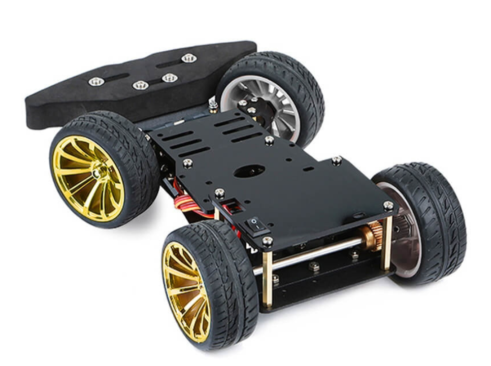
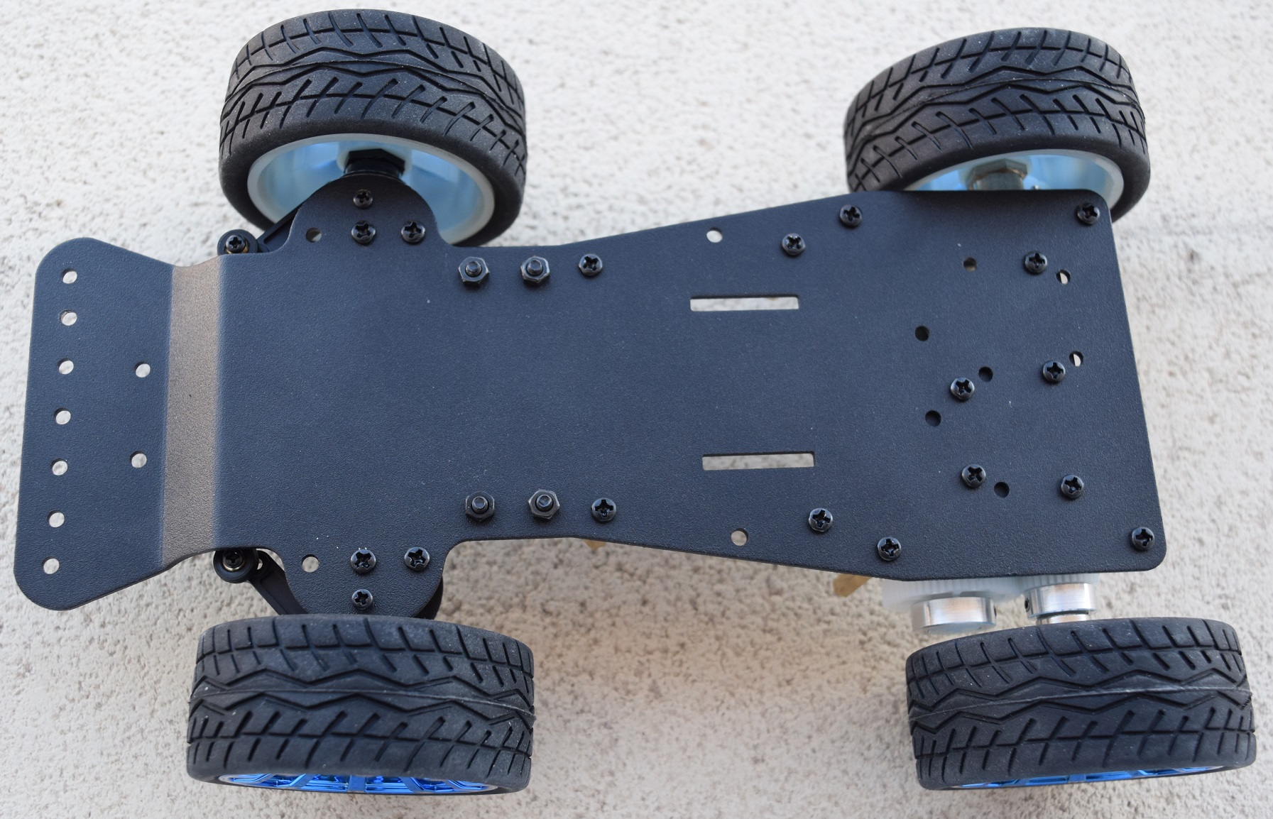
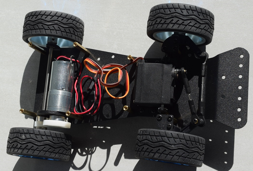
This is a classic rear-wheel drive car with
two-wheel drive with motor provided and front steering controlled by a servo
motor also provided.
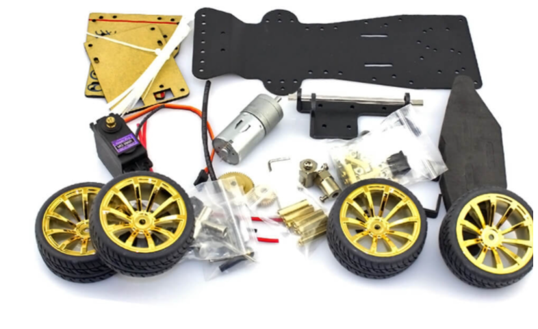
Pre-drilled metal chassis, 2 resin plates, motor and gears for the rear
driving wheels, servomotor to control the front steering, screws, bearings,
various accessories...
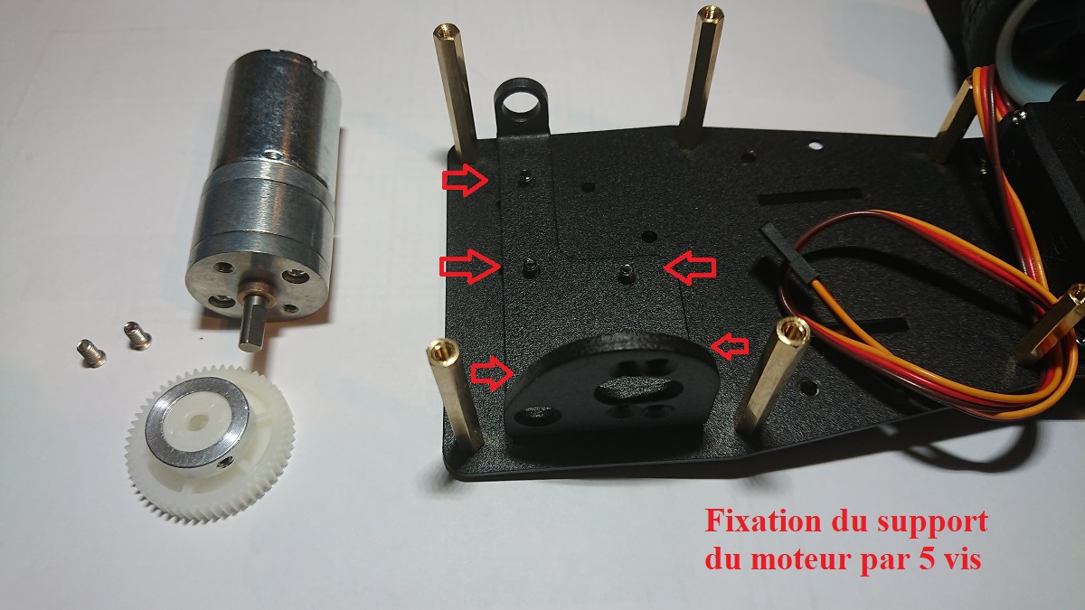
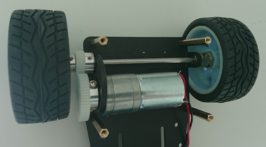
Securely secure the engine and rear wheel
support using 5 screws
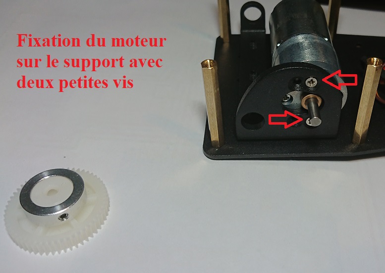
Fix the pinion to the output of the motor shaft
using 2 recessed screws, be careful to place the flat area of the
shaft facing one of the screws
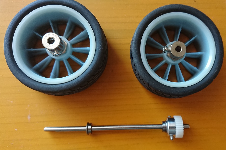
Prepare the parts making up the rear axle of
the car
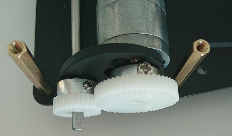
Place the rear axle like this without
forgetting the two small bearings which fit into the support, securely fix the
small pinion using the recessed screws
Please note, the two
sprockets can be installed in both directions but tightening with the screws is
only effective in the direction above
(Indeed, especially with regard to the large motor output pinion, it is
impossible to tighten the screws correctly if you reverse its mounting
direction on the axis, the screws do not reach the axis which rotates in a
vacuum without driving the rear wheels!)
Put the rear wheels in place
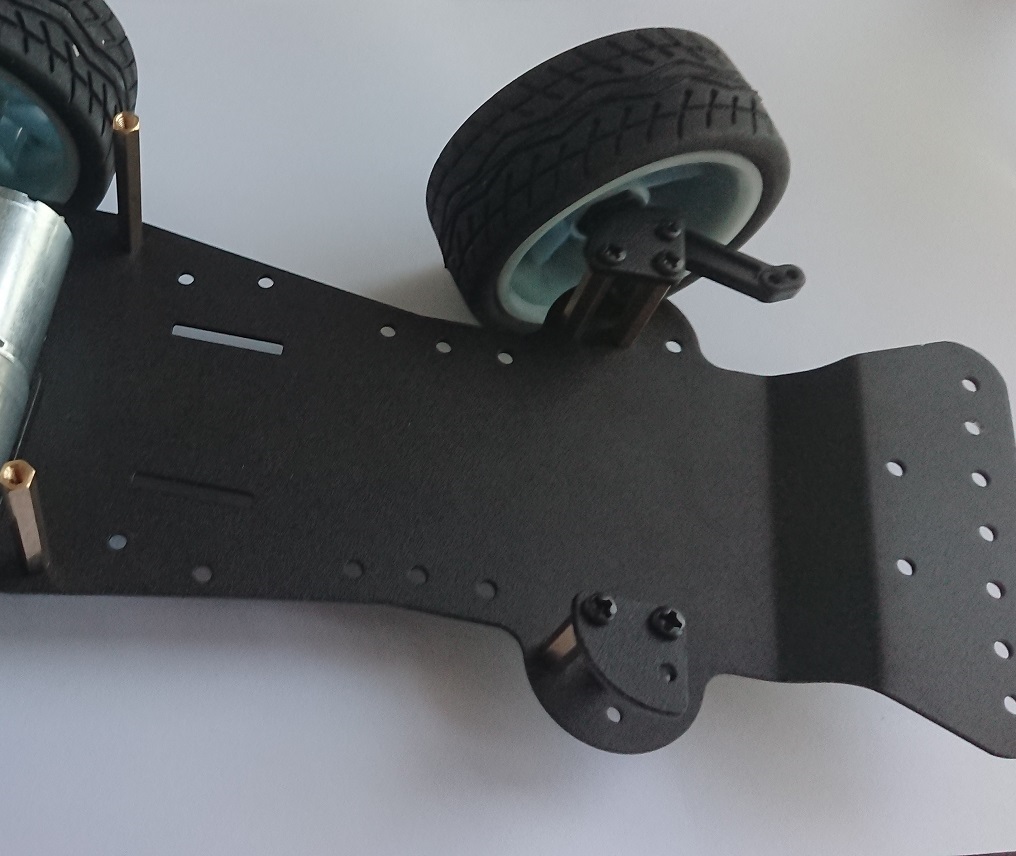
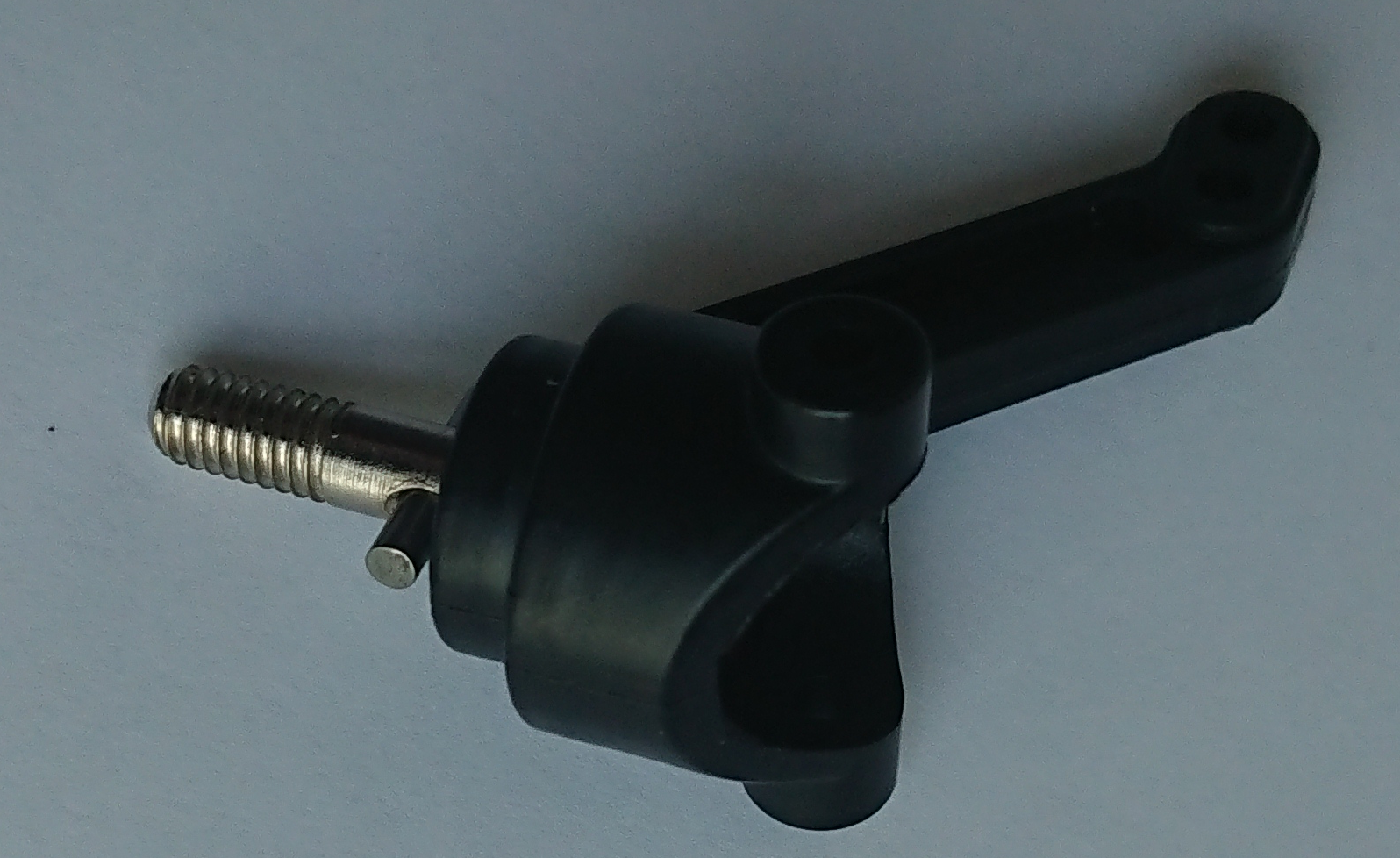
Prepare supports for the front wheels and
steering system
Front wheel assembly assembly details
Chassis returned with screwed fixings
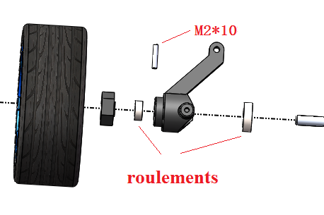
Parts used for the front wheel
mounting system
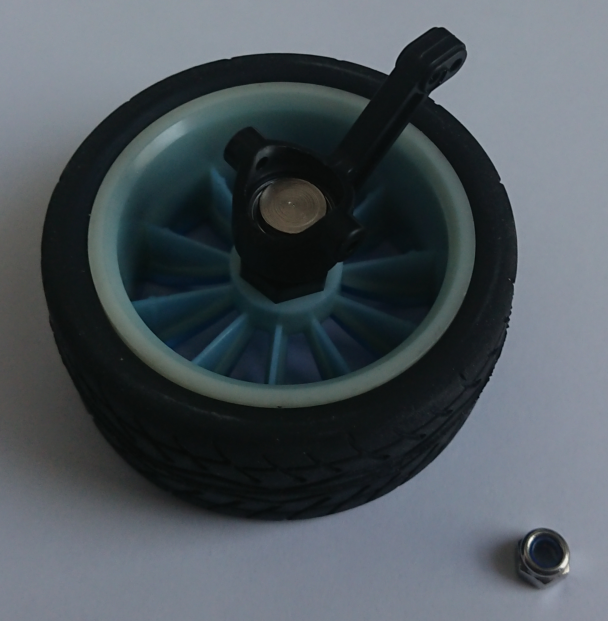
Front wheel support and details
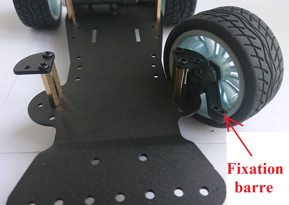
Fixing hole for the future steering bar
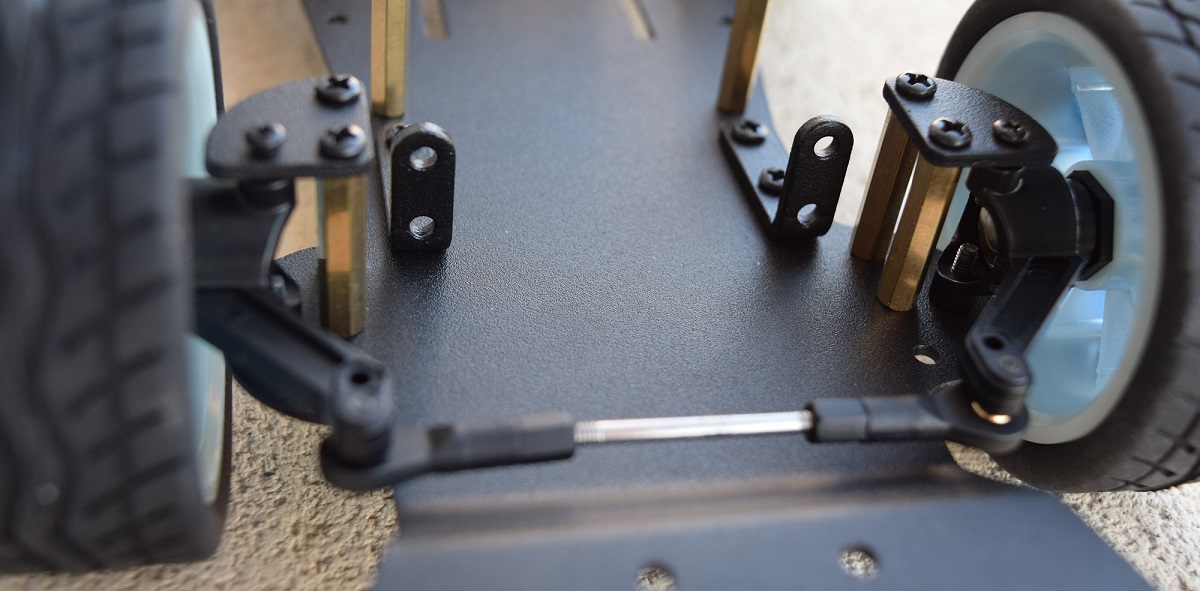
Front wheels placed and connected by a steering
bar with adjustable spacing by screwing
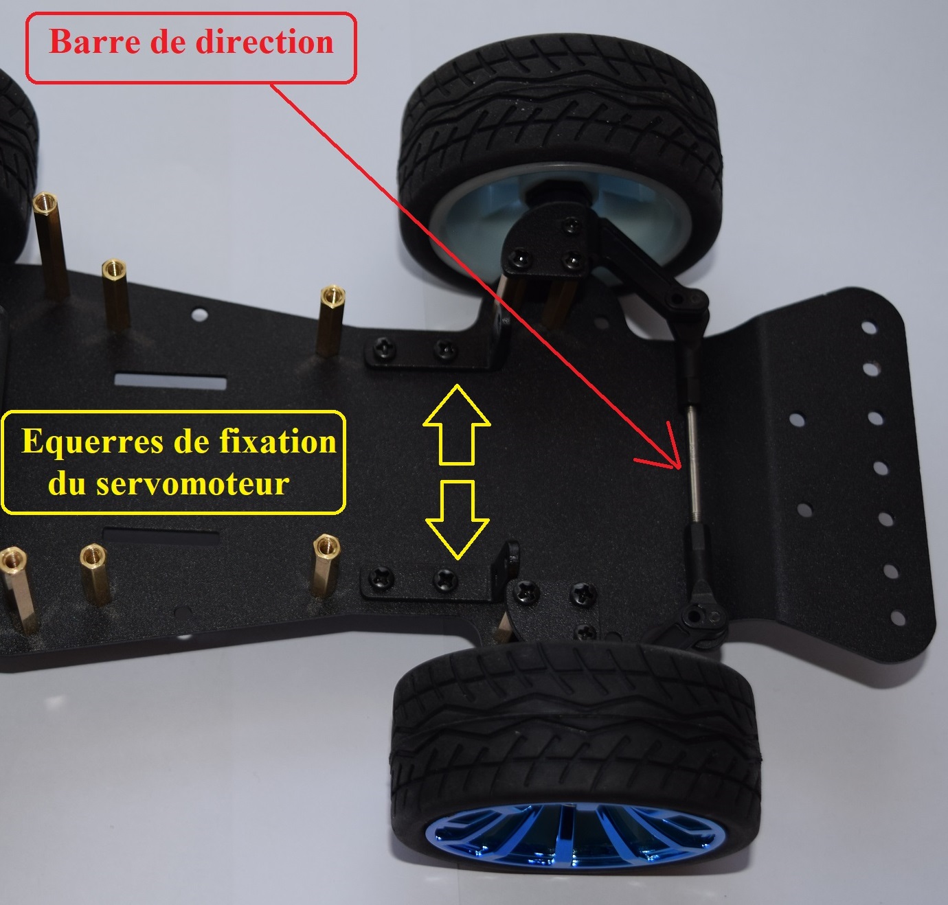
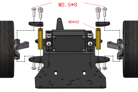
Brackets intended to securely fix the servomotor
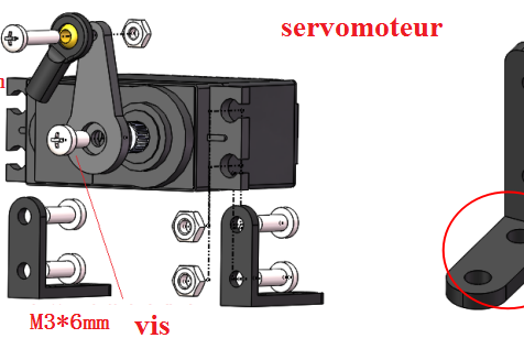
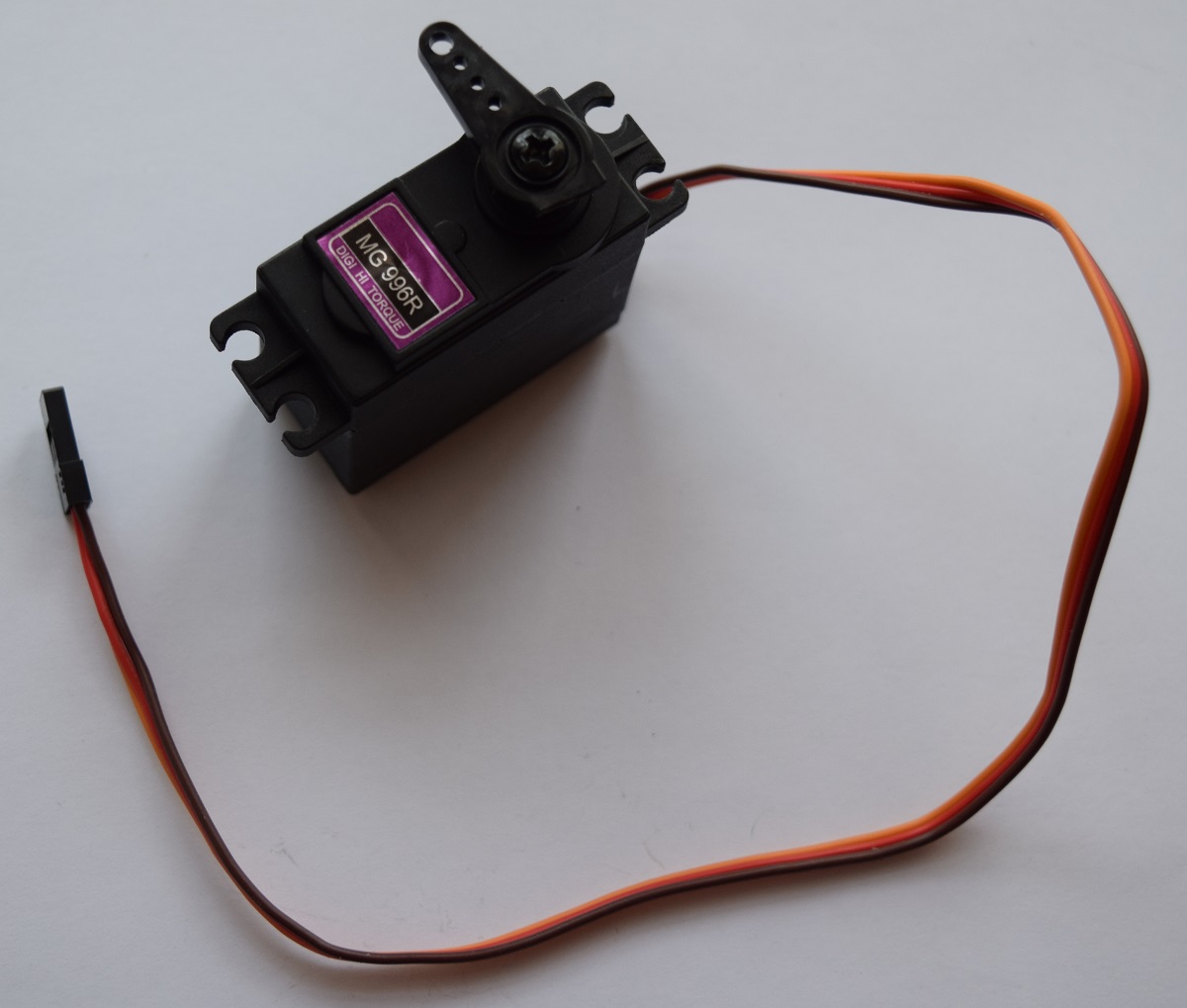
Servomotor before mounting on the chassis
Servomotor securely screwed onto the two brackets
You must position the movable arm halfway
through the motor stroke before screwing it securely!
It must be able to turn approximately 90° to
the left and 90° to the right.
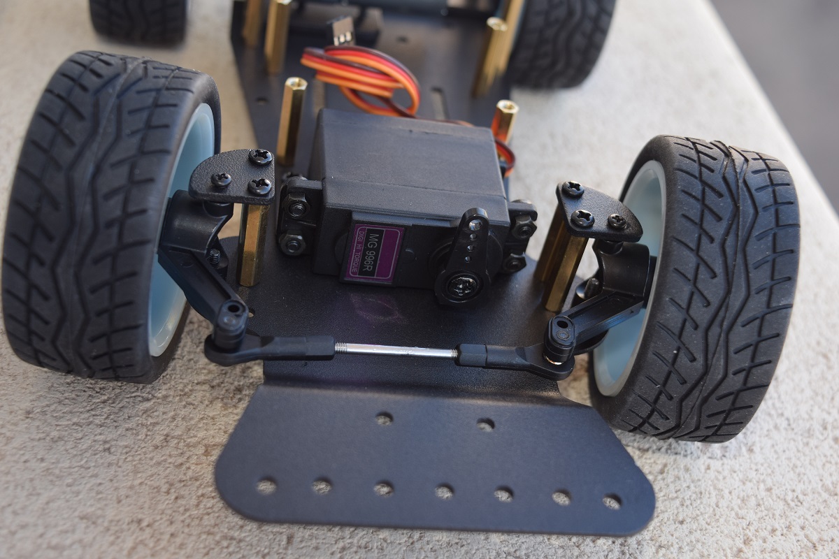
Servomotor installed and
screwed onto the two small metal brackets
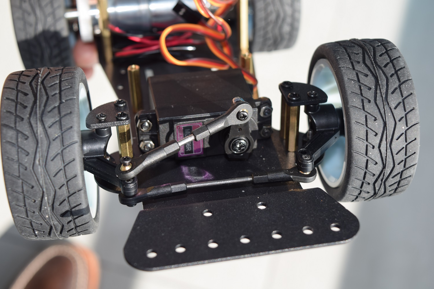
Installation of the adjustable
link connecting the servomotor arm to the steering bar
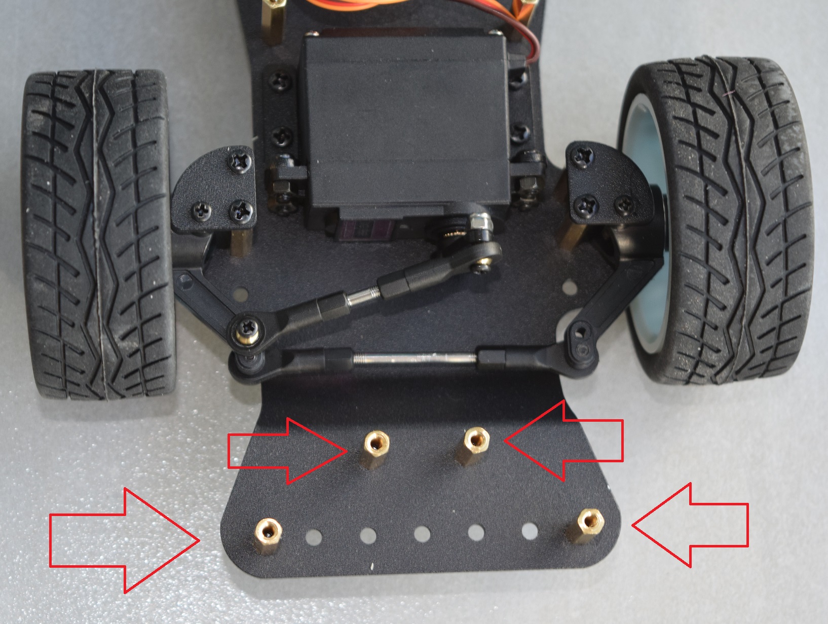
Preparing to attach the front shield
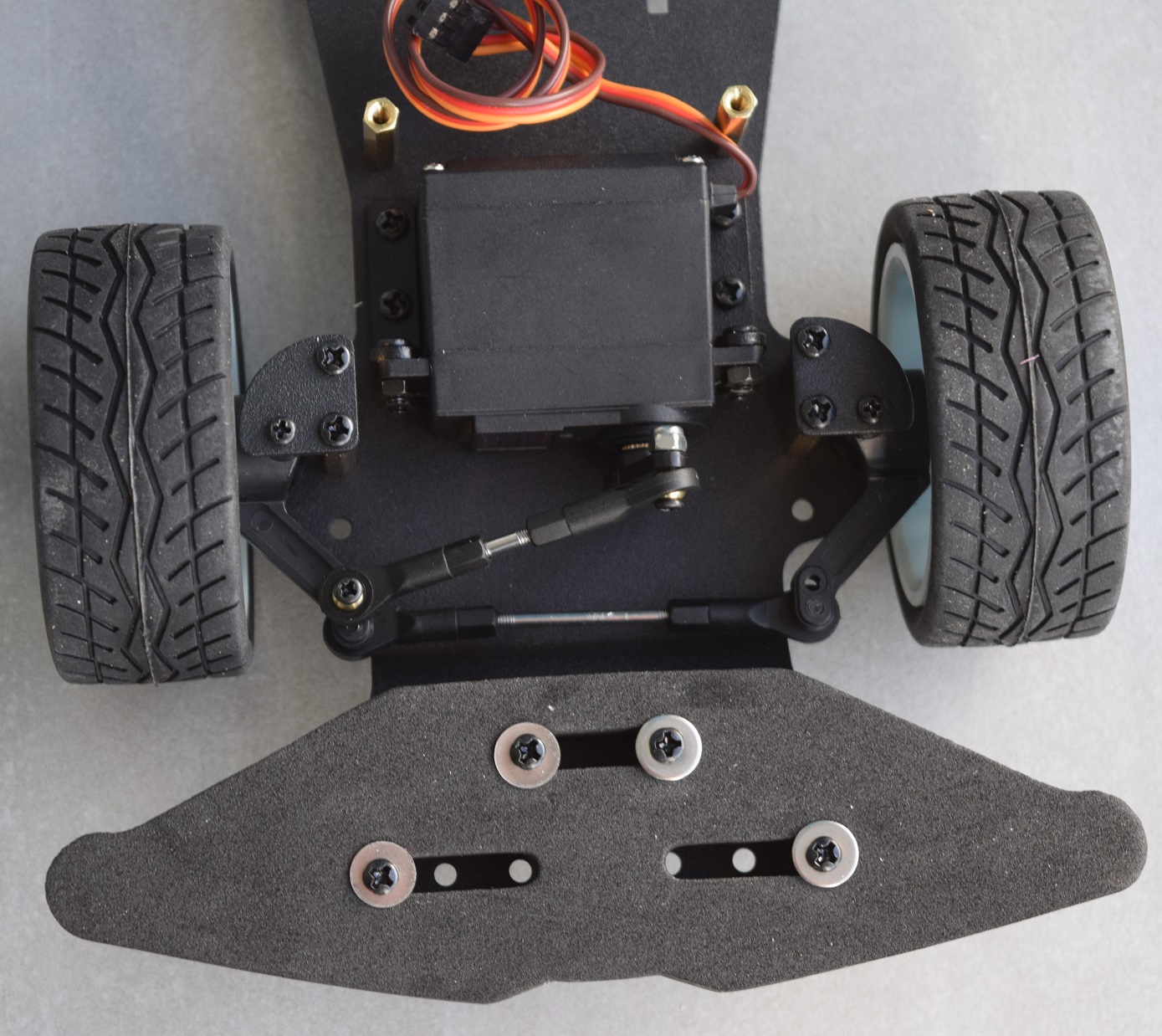
Front shield installed
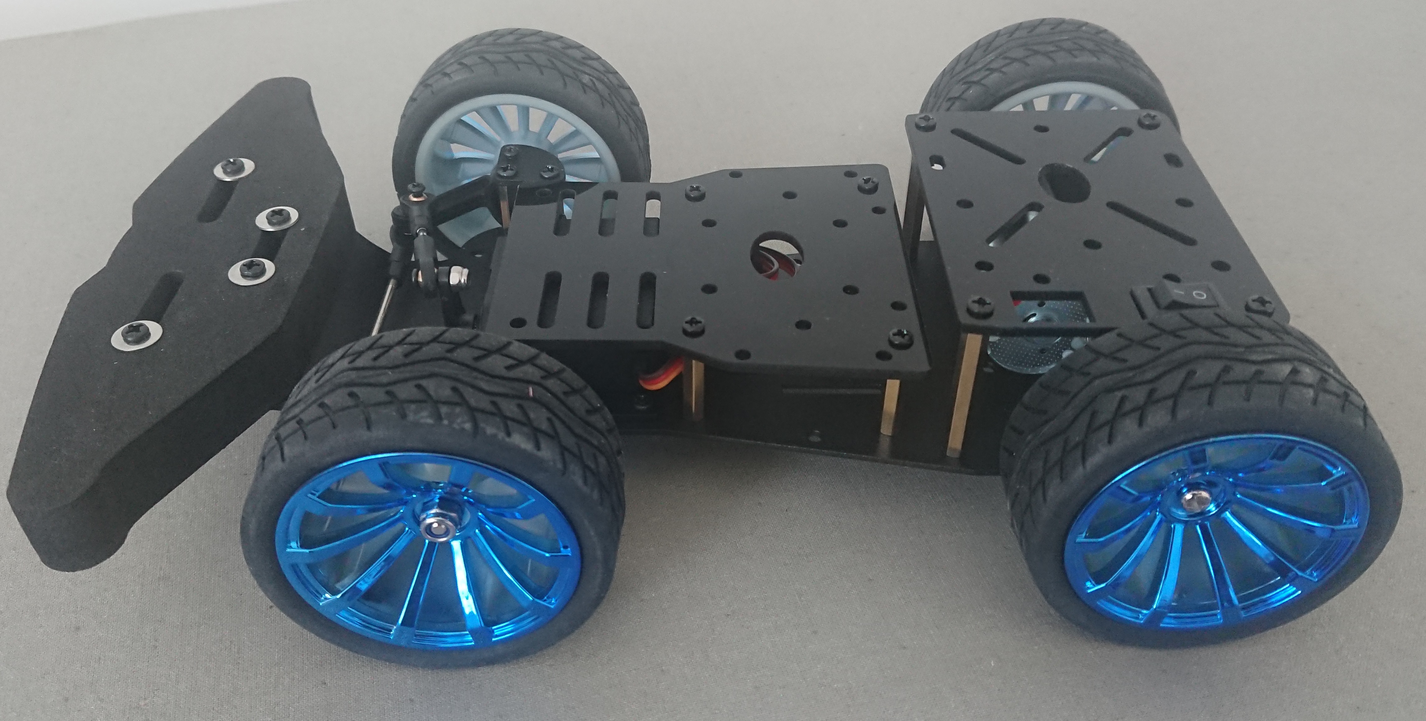
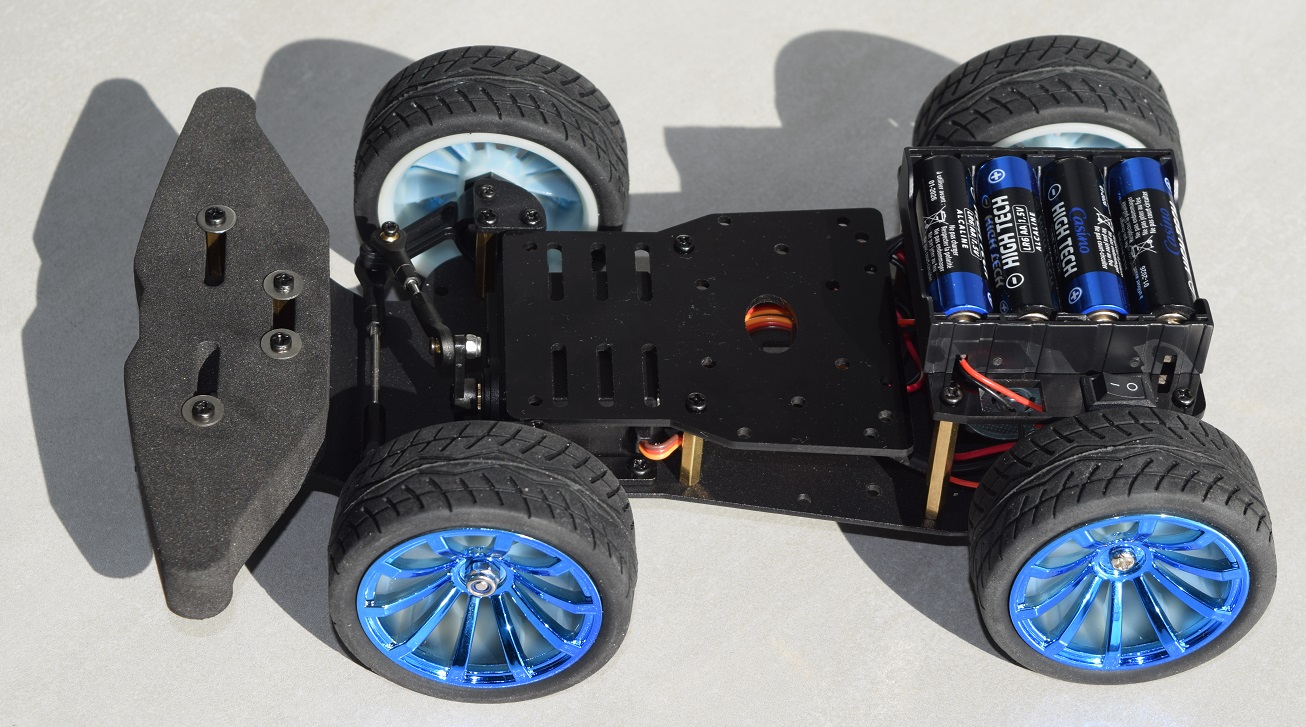
Installation of the two resin
plates and the small general switch on the rear plate