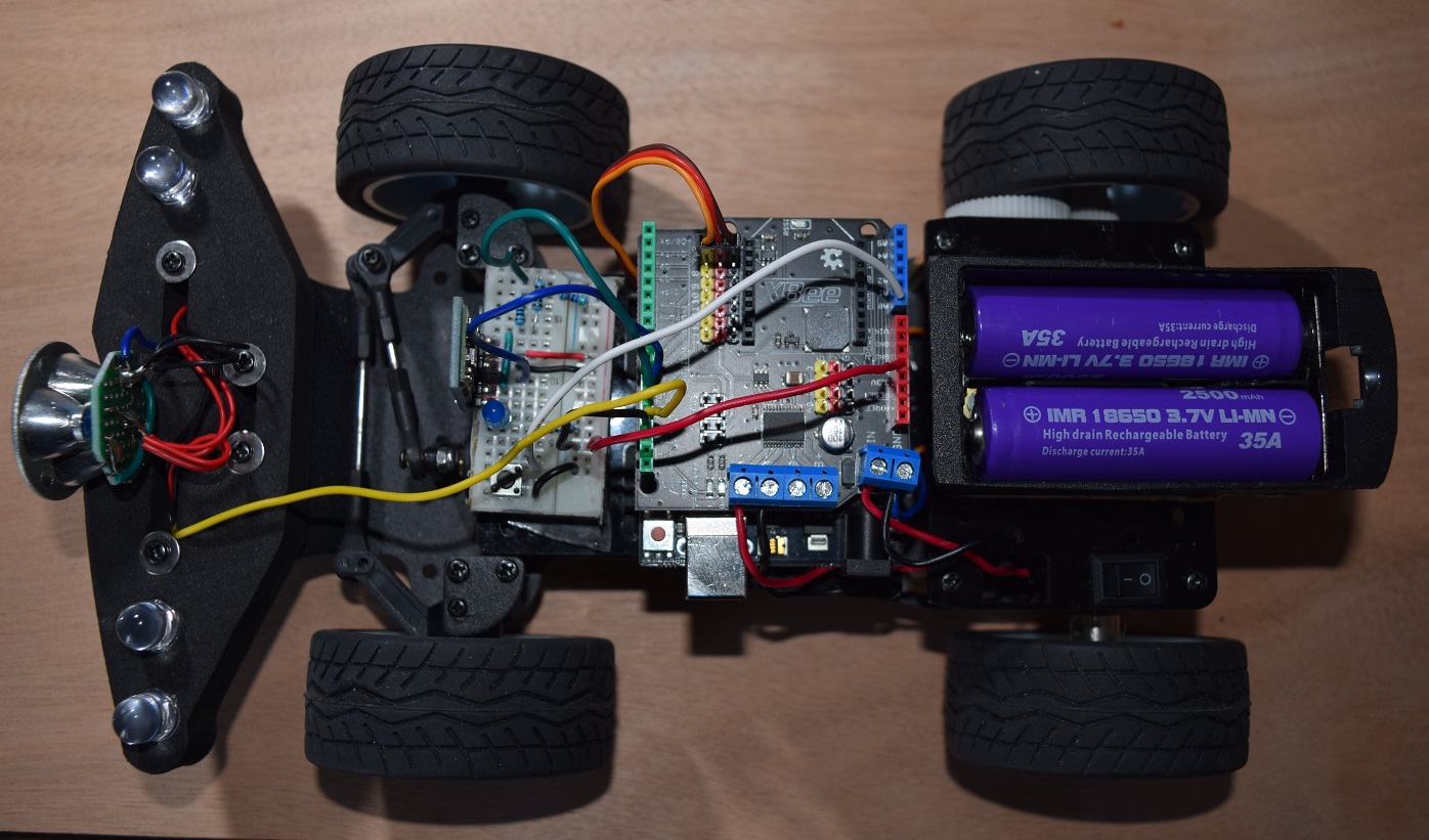
Electronic
equipment of the car
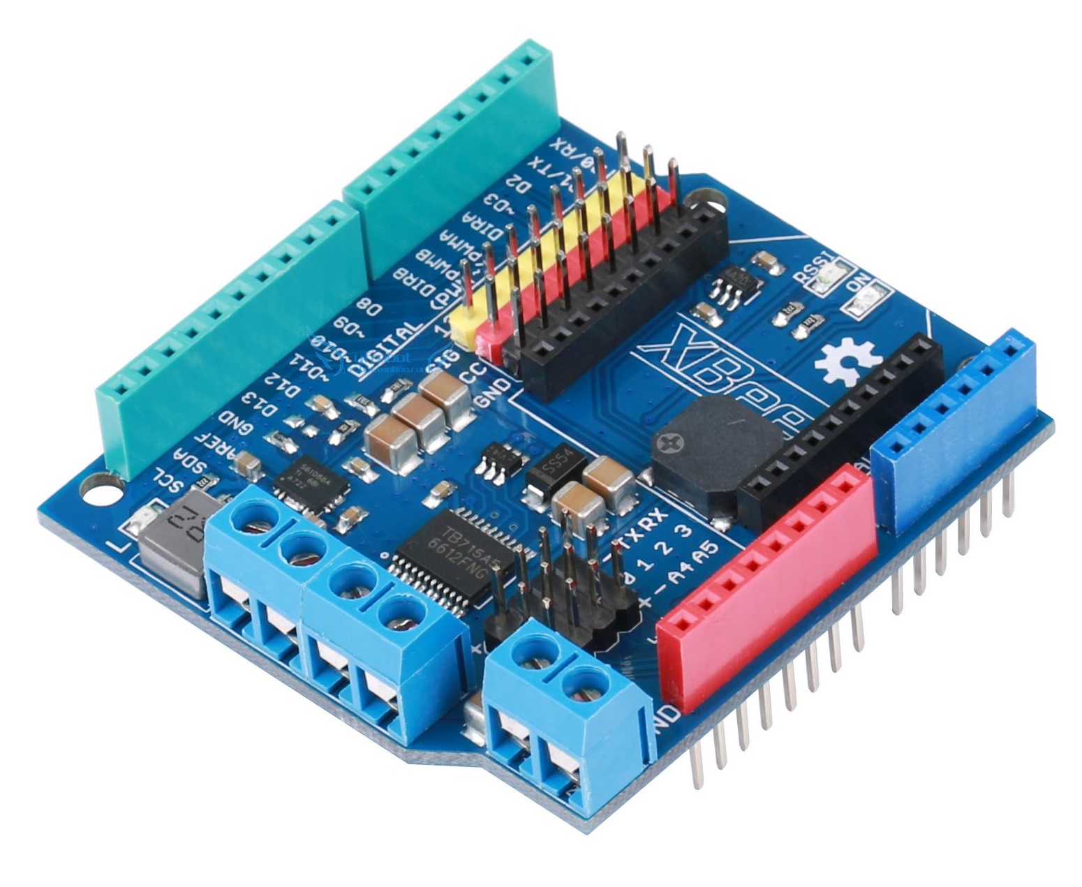
with Arduino UNO board + YFROBOT XBee PM-R3
shield
 OR
OR 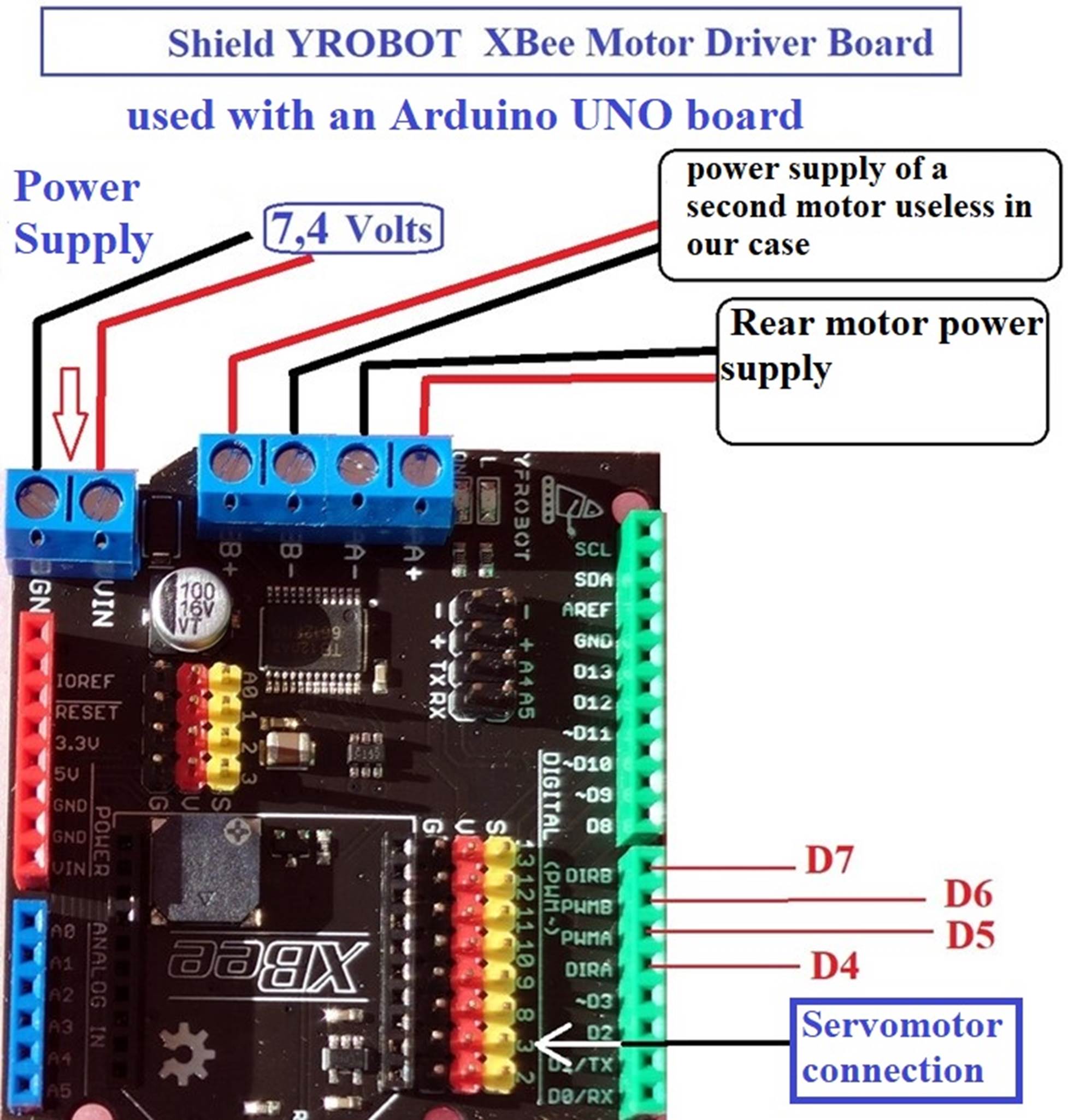

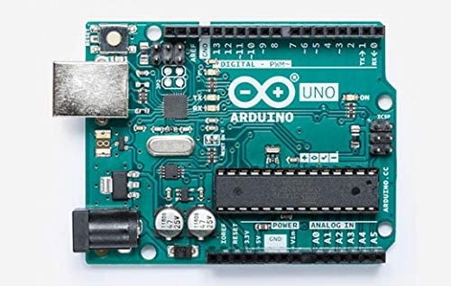
- An Arduino UNO board or similar
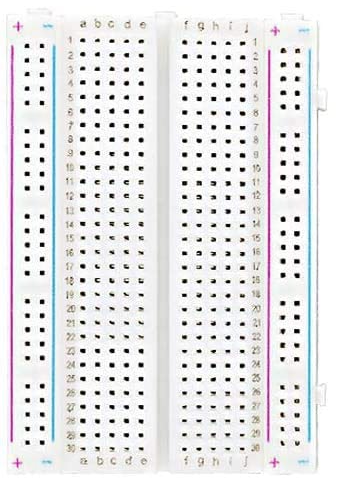
- Half a connection plate (which will be reduced to
the dimensions available above the servomotor)
- A YFROBOT XBee PM-R3 Motor
Driver “shield” card
Supplier Links:
https://www.sinoning.com/product/yfrobot-pm-r3-smart-car-drive-board-r3
https://www.ebay.fr/itm/182826494617
OR Hailege ARDUINO UNO
R3 Shield L298P
https://www.amazon.fr/dp/B07XG64D13?ref=ppx_yo2ov_dt_b_fed_asin_title
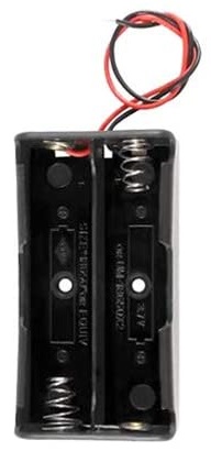
A holder for 2 18650 Li-ion lithium batteries
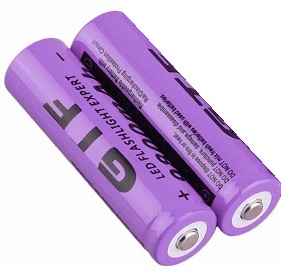
- Two Li-Ion 18650 rechargeable batteries of 3.7 volts
each
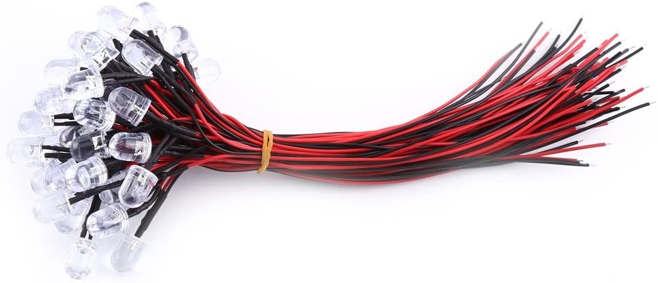
- 3 1KΩ resistors, 1 220 Ω resistor, 1 blue LED, white
LEDs to place at the front, 2 red diodes to place at the rear
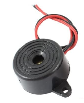
- 1 buzzer which will serve as a horn
- Colored cables, jumpers for the various connections
between all these elements
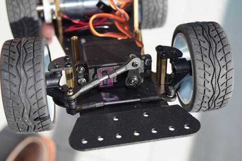
Remember that the motor (rear
wheel propulsion), the servomotor (front steering management) and the general
switch were provided in the original kit.

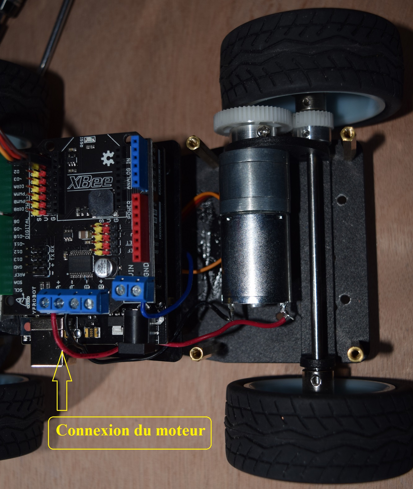
Connecting the rear motor to
the YFROBOT board installed on the ARDUINO UNO board pins
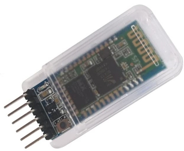
There is no change from car #1
regarding the HC-05 Bluetooth module and the small button to start the tests
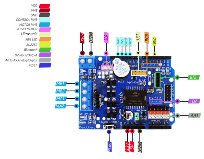
Detail of the pins and
connections of the YFROBOT XBee shield card
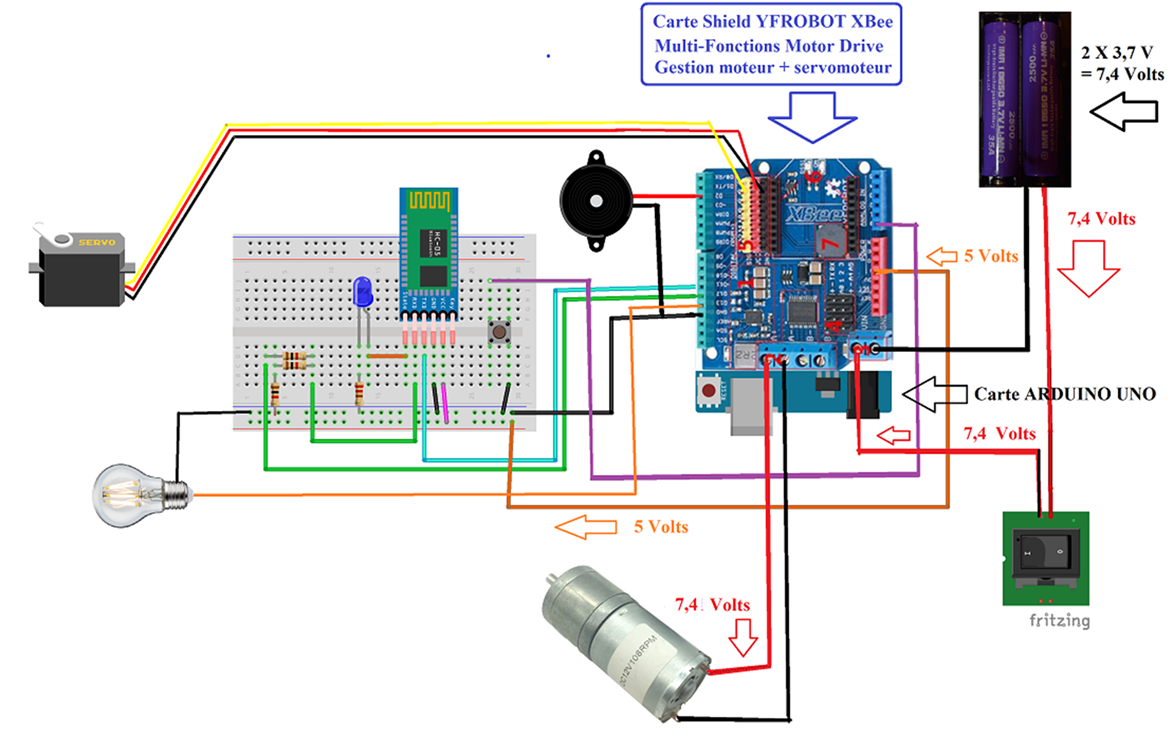
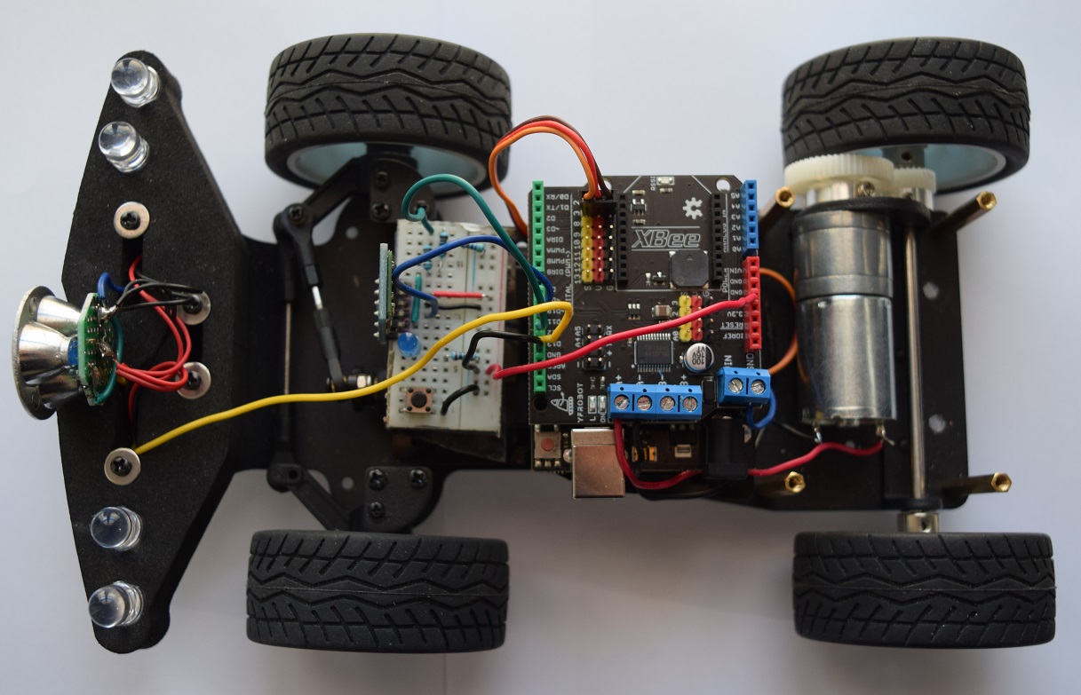
General connection diagram for
the arduino car
The new B4R program has been adapted
to the new components used but the algorithm is essentially the same as that of
the previous program concerning car no. 1.
The essential changes are due to the specificities of
the YFROBOT card used, the pins of which are preconnected in an internal
circuit.
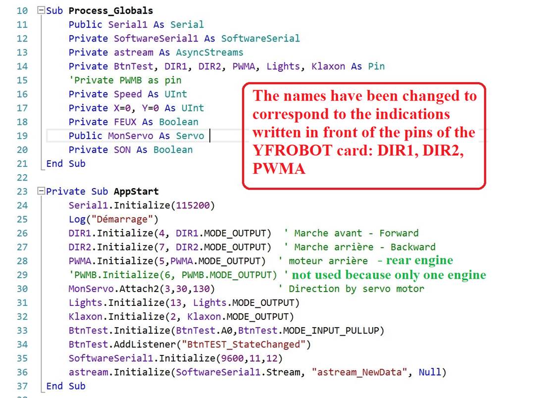
I modified the names used to simplify the programming and adapt it to the indications given on the card itself. Here are some significant extracts from these changes:

Excerpts from the
B4R code of the program adapted to car no. 2
So IN3, IN4, ENB became DIR1, DIR2, PWMA…
Steering pins:
DIR1 >>> Pin D4
DIR2 >>> Pin D7
Motor speed:
PWMA >>> Pin D5
(Note that if we used a second motor, its speed would
be managed by PWMB on pin D6)
Servomotor >>> Pin D3
No changes for the management of lights (Pin D13) and
Horn (Pin D2) nor for the test button connected to analog pin A0.
The HC-05 Bluetooth module is always connected to pins
D11 and D12.
Download
the B4R File Download
the B4A file